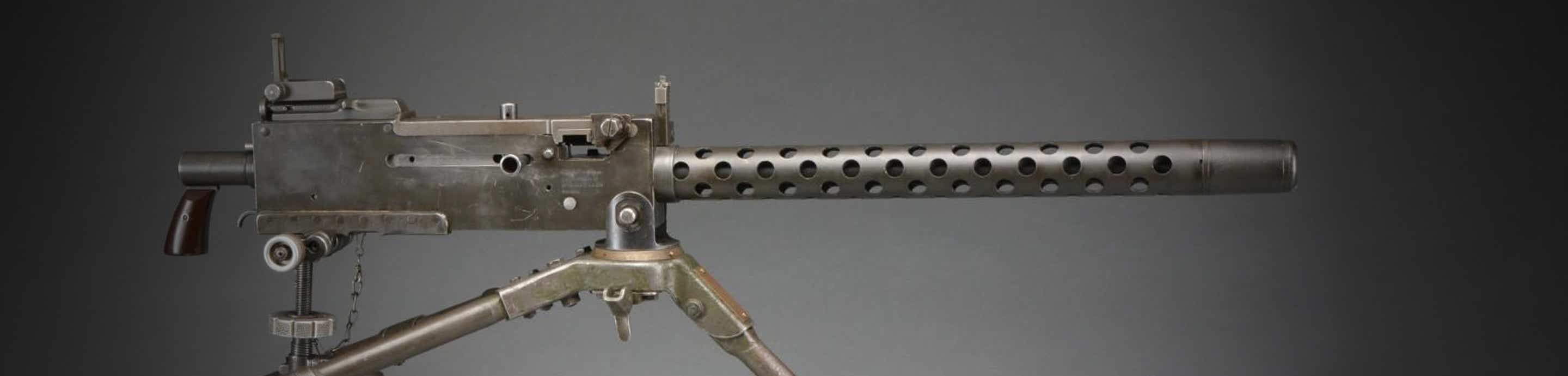

Like many others that came before me, I'm looking for arsenal blueprints for the trunnion. I'm not sure why it seems to be so closely guarded, but I'm having a hard time locating it (I have the rest - almost). I have no intentions of making them (I probably could I guess, but it's likely cheaper to buy). I simply collect blueprints and want to make a dimensionally accuarate M2HB model.
I'm not asking someone to fork it over out of the goodness of their heart though (since you might have paid for it yourself); how about a trade? I have quality scans of the original prints for the AK-47 front trunnion that I'd trade. If you're a builder (or just a fan of AK's), you probably know that you can easily reverse-engineer the majority of the trunnion...with the exception of the 3 bolt lugs. This print tells all the secrets of getting it right the first time. (I can also provide info on how they're originally manufactured as well).
For the print I'm after, like I mentioned, I want scans of the original (the rest of mine are a mixture of Rock Island and US Army Armament Research and Development Command).
-WRM